Bespoke Solutions
Certified Quality Solutions to Meet Every Lifting Challenge
We design, manufacture, certify and install custom-built bespoke lifting solutions to tackle any lifting requirement. Whatever your lifting challenge, we can design and build a solution to address your needs. Our comprehensive service takes you through every step of the process, from initial drawing and design to manufacture, testing, certification and installation of your new equipment on site. While the quality of our design and fabrication distinguishes us from other providers, what really sets us apart is our verification process. Every piece of equipment we produce comes fully tested and certified, giving you peace of mind, and tangible proof, that it is fit for purpose.
Bespoke Lifting Solutions
Take a look at some of our recent work >


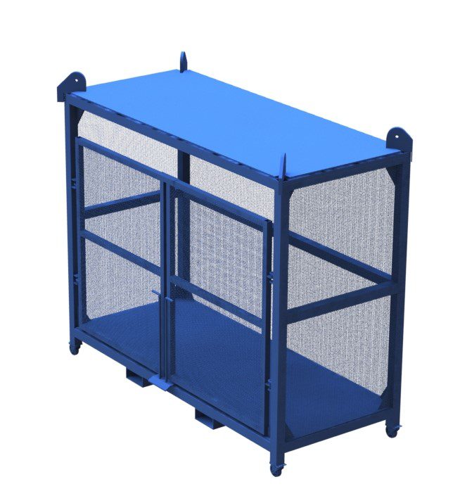
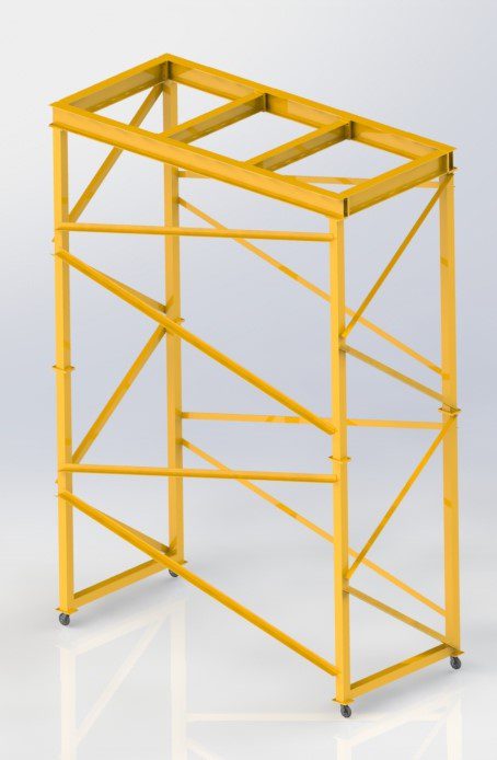
3T Pallet Cage – ISO View
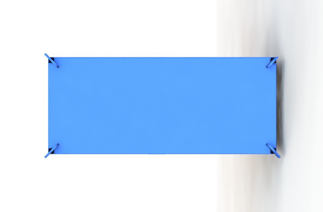
3T Pallet Cage – Top View
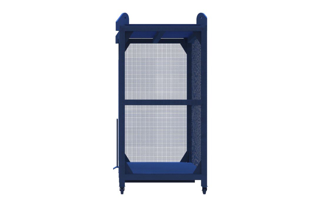
3T Pallet Cage – Side View
3T Pallet Cage – Elevation
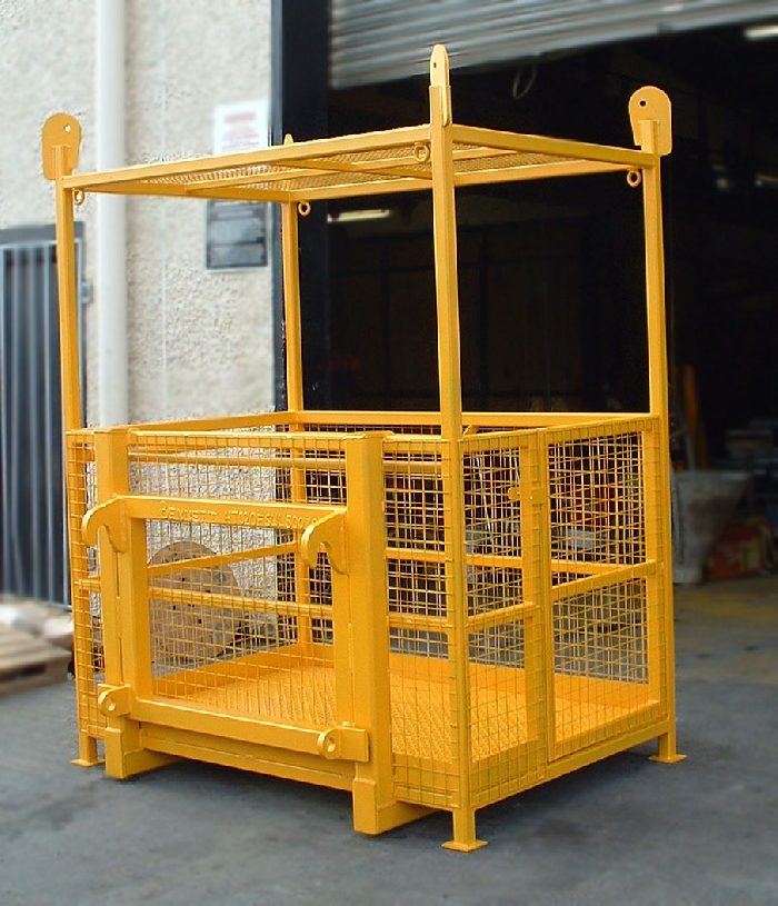
3 Tonne Pallet Cage for shipping vessel
- A lifting capacity of 3,000kg was required
- The cage had to be capable of containing two standard size pallets side by side
- The cage had to be capable of being transported by a variety of different means.
- The cage had to have an enclosed roof to prevent damage to cargo due to falling objects.
Solution
- 2 No. Lockable doors with spring loaded locking pins.
- Weld mesh wall sections to prevent any cargo from falling free.
- Lifting Lugs on top of the cage to allow it to be loaded and unloaded from a ship using a dockside crane.
- Fork Pockets to allow it be transported using a standard fork truck
- 4 No. All swivel all brake castors for movement using a single operator.
- Increased Roof struts to prevent any crush damage should cargo fall on top of the cage.
Forktruck Attachment
- The boom attachment was required to be able to operate at capacities of 500kg to 2,000kg.
- The boom attachment was required to be able to operate at distances from the base of the fork blades from 1200mm to 2500mm
- The boom attachment needed to be adjustable by one operator.
Solution
The solution provided was an adjustable boom attachment complete with:
- 2 No. Heel pins to lock the attachment into position.
- A sleeved adjustable boom complete with safety pin locking mechanism.
- A maximum SWL of 600kg at 2750mm from the base of the fork blades.
- A maximum SWL of 3,000kg at 12000mm from the base of the fork blades.
Forktruck Boom Attachment – Elevation
Forktruck Boom Attachment – Iso View
Forktruck Boom Attachment – Side View
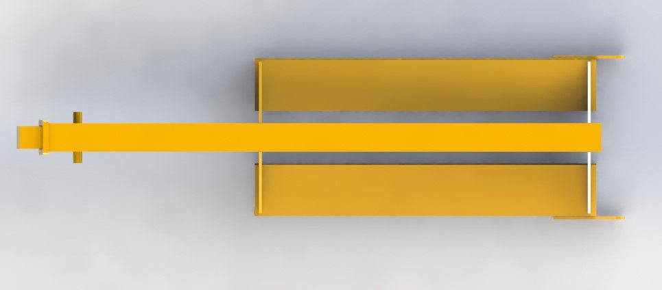
Forktruck Boom Attachment – Plan View
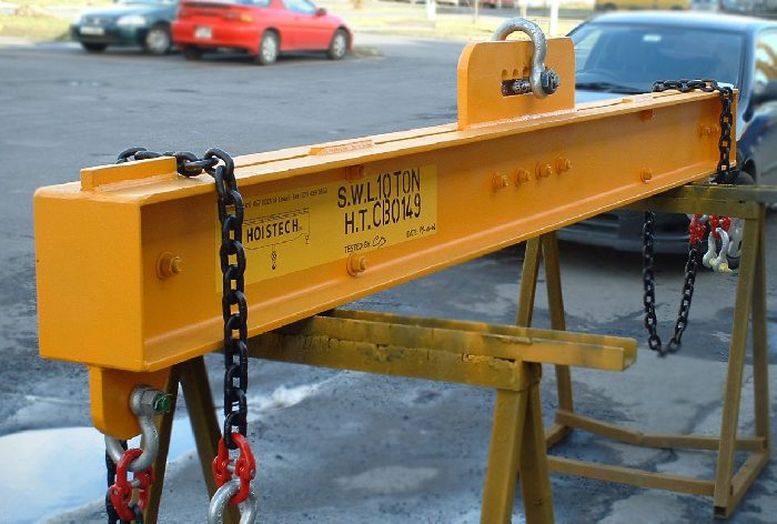
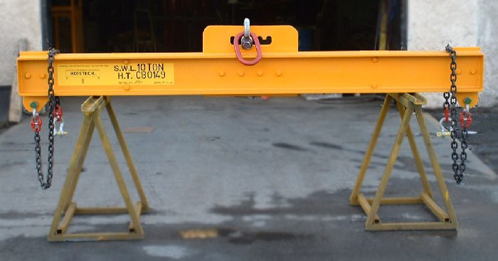
The Spreader Beam
The following requirements were noted prior to the design of the Spreader Beam:
- A lifting capacity of 500kg was required
- The spreader beam had to be capable of extending to 3 different lengths from 2.0m to 3.0m
- The beam had to be capable of being assembled by a single operator so light weight design was key.
Solution
- A SWL of 500kg
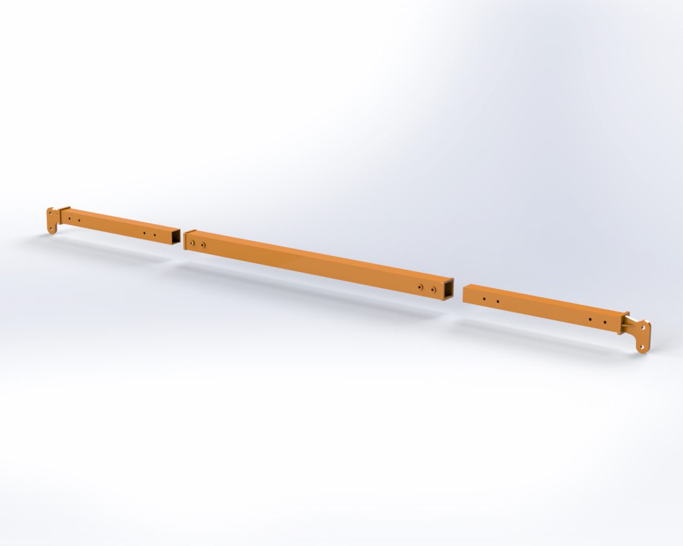
- Sleeved Box Section Arms to allow to it to be extended in length.
- Lifting Lugs set in line with the line of force of the beam to reduce bending forces applied to the beam.
- Alight weight design which allowed for the beam to be assembled and disassembled by a single operator.
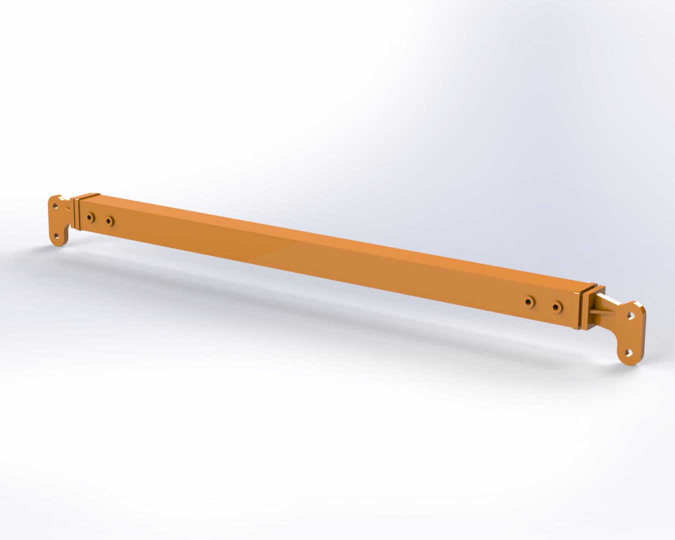
Iso View
Plan View
Side View
Elevation View
Straddle Carrier
- A lifting capacity of 2,000kg was required.
- The straddle carrier had to be capable of a height of lift of 6.0m in order to allow for a large AHU to be lifted up through an opening in the floor level below.
- The straddle carrier had to be capable of being manoeuvred into position unladen by 2 operatives.
- The straddle carrier had to be capable of mounting 4 No. Chain Blocks to lift the AHU.
Solution
- A SWL of 2,000kg
- A 2 Stage assembly design to allow it to be brought into the room in sections and assembled over the floor opening.
- 2 No. beam sections to mount 4 No Chain Block/Trolleys for lifting.
- 4 No. all swivel all brake castors to allow the straddle carrier to be moved over the opening and locked into position during lifting.
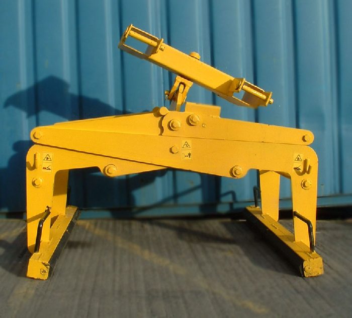
Barrel Lifting Frame
- The lifting frame required a low headroom profile to accommodate existing height restrictions in their facility.
- The lifting frame required a mechanism by which to easily manoeuvre the barrels into position and then securely strap them into position.
- The frame was required to be light weight so as to be placed into storage by means of manual handling when required.
Solution
The solution provided was a low profile barrel lifting cage complete with:
- Round Bar Top Lifting Point to engage directly with the crane hook.
- Light weight Box Section Frame.
- Hinged strapping mechanism to secure the barrel during movement.
Barrell Lifting Cage – Side View
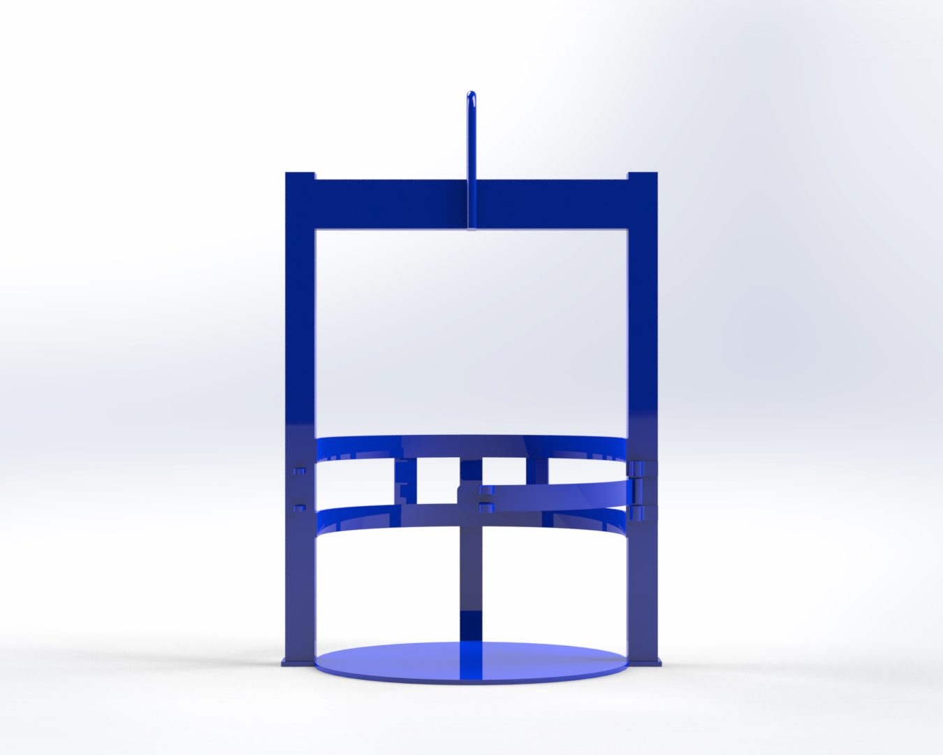
Barrell Lifting Cage – Front View
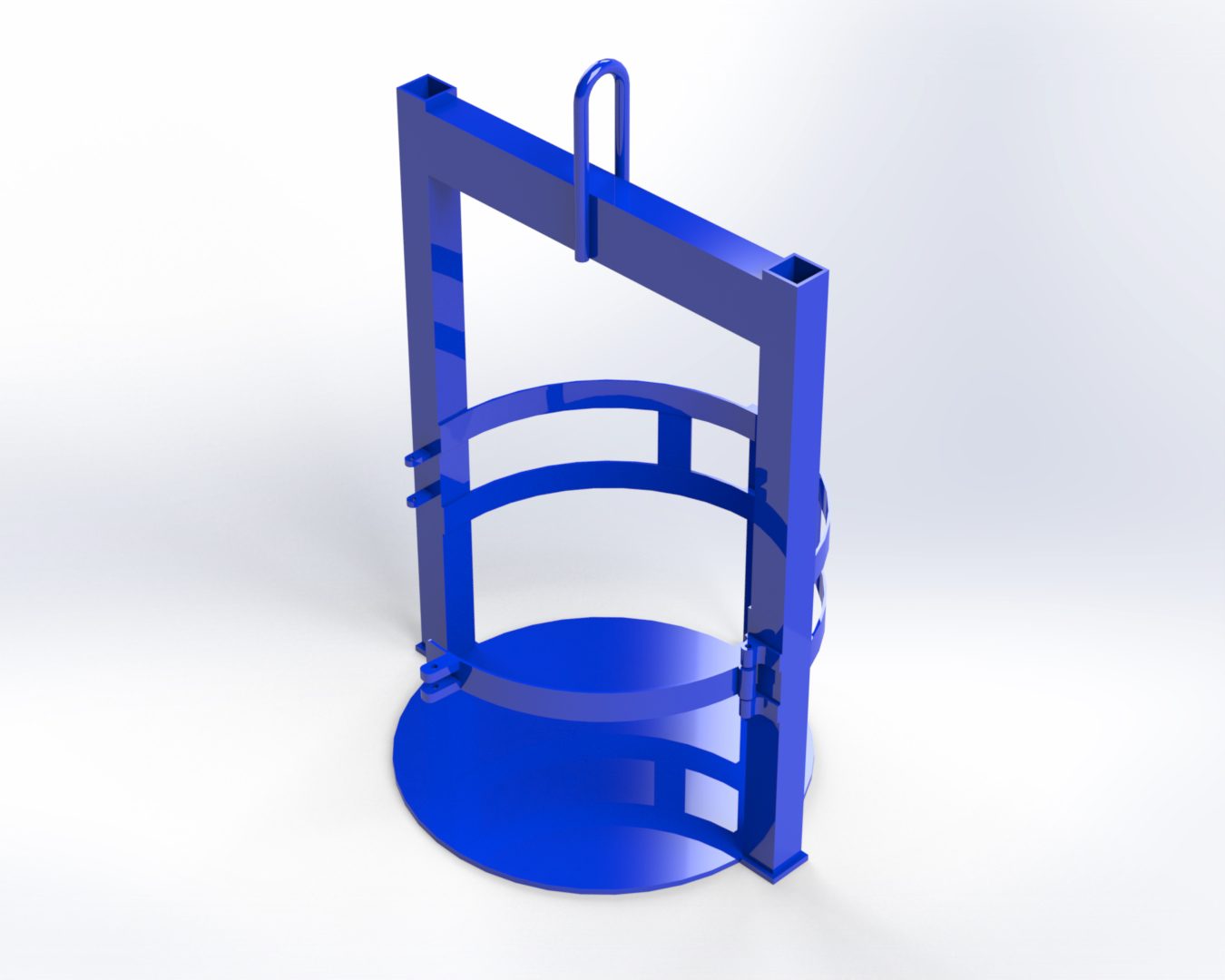
Barrell Lifting Cage – Isometric View
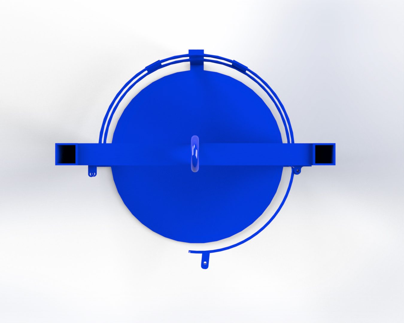
Barrell Lifting Cage – Plan View
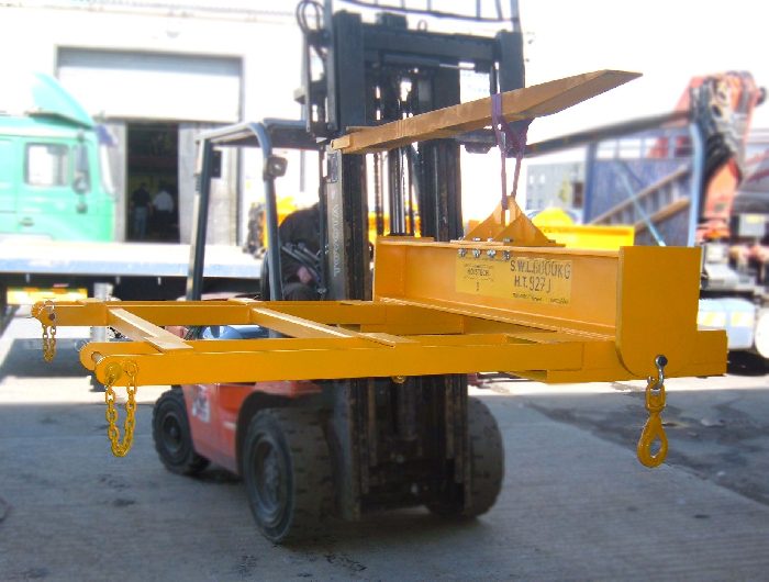
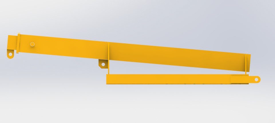
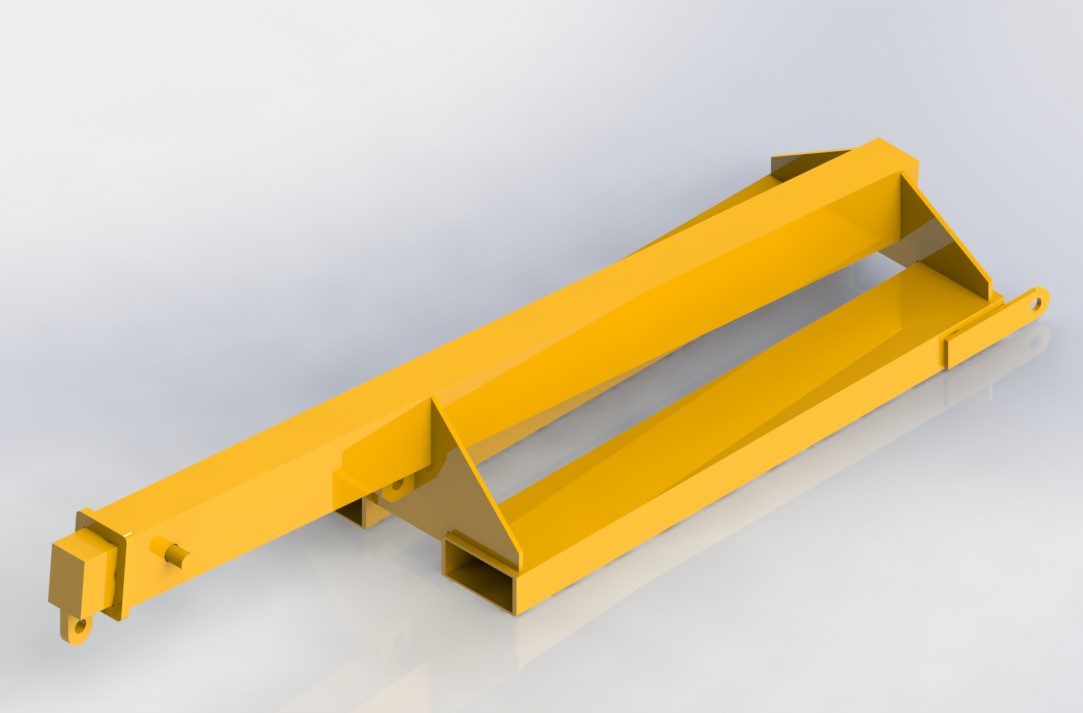
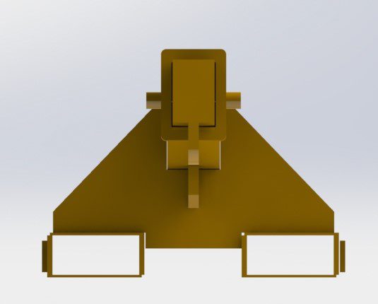
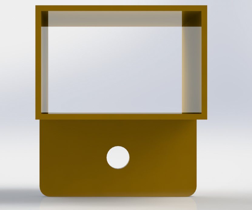
Fork Lift Attachment
Requirements
The following requirements were noted prior to the design of the Forklift Attachment
A lifting capacity of 1,500kg was required for the maximum lift.
- The Fork Attachment was required to by suspended from a single fork lift blade.
- It was also required to connect to a single 4.7T Safety Bow Shackle to allow additional rigging to be utilised.
Solution
The solution provided was a Bespoke Fork Lift Attachment complete with…
- A SWL of 1,500kg
- A RHS Sleeve designed to be used with the fork blade dimensions of the clients existing equipment.
- 1 No. 4.75T Safety Bow Shackle affixed to the unit to allow for a variety of rigging options to be used with the attachment.
- RAL-1007 Yellow Painted finish.

Fork Attachment – Elevation
Fork Attachment – Side View

Fork Attachment – Plan
Fork Attachment – Iso View
Steel Beam Mounted Lifting Eye – Iso View

Steel Beam Mounted Lifting Eye – Plan View
Steel Beam Mounted Lifting Eye – Side View
Steel Beam Mounted Lifting Eye – Elevation
Lift Shaft Eyes
Requirements
- A lifting capacity of 3,000kg was required
- The Lift Shaft Eyes had to be capable of being bolted into existing steel support beams.
- The Lift Shaft Eyes had to be capable of being connected to using a shackle/safety hook.
Solution
- A SWL of 3,000kg
- A 4 hole design to bolt to the bottom flange of the beam on either side of the web.
- 4 No. M16 Mechanical Anchors provided with the Lift Shaft Eye.
- RAL-1007 Painted finish to highlight the tested lifting point.
Chime Lifting Frame – Affixing Brackets
Chime Lifting Frame – Anchor Point
Chime Lifting Frame – Elevation View
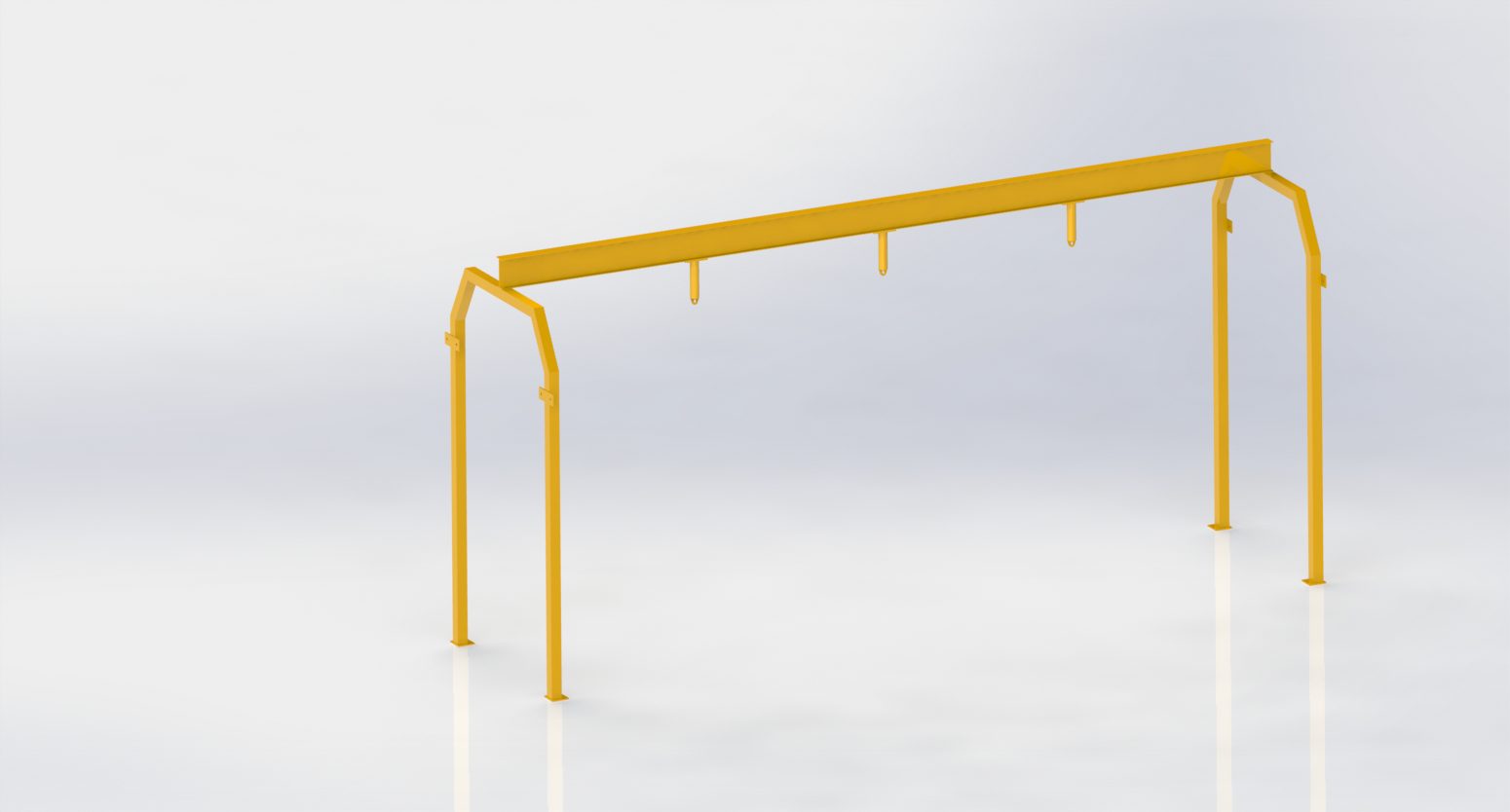
Chime Lifting Frame – Iso
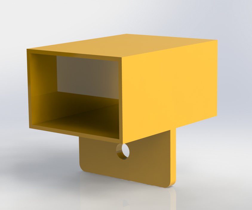
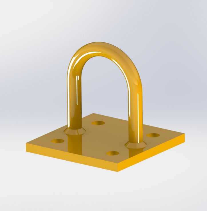
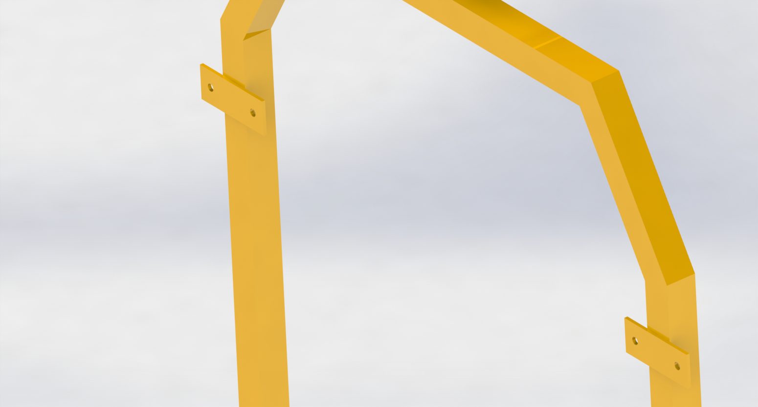
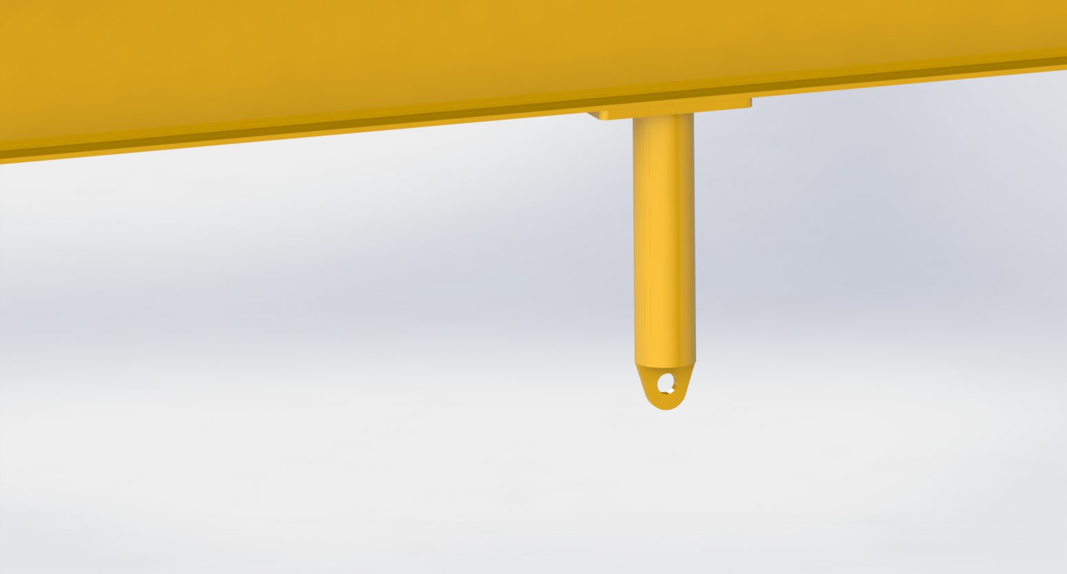
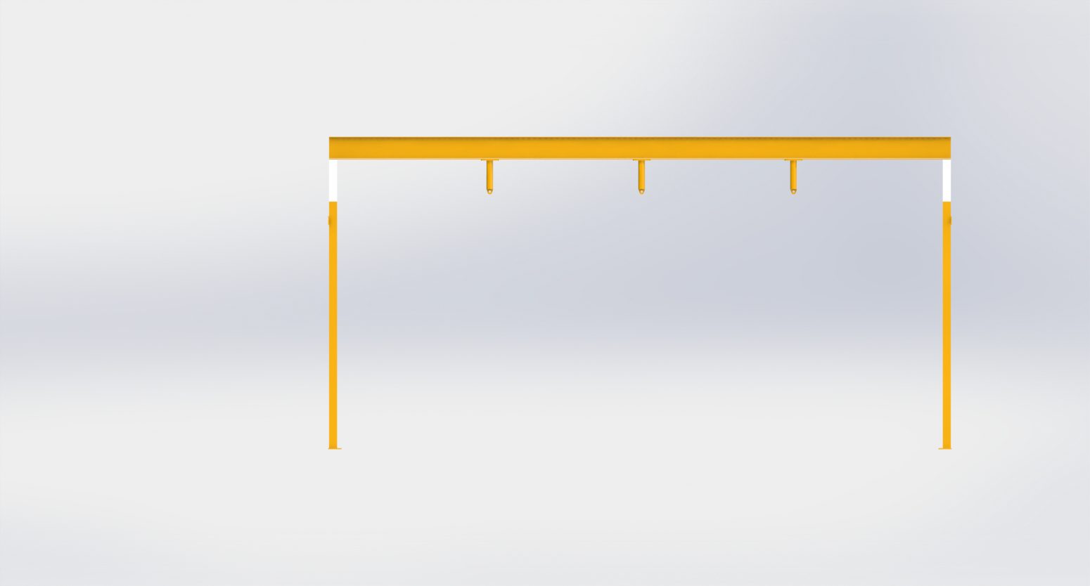
Sensory Room Swing Frame
Requirements
The following requirements were noted prior to the design of the Sensory Room Swing Frame
A lifting capacity of 3 persons was required for the maximum lift.
- The Swing Frame was required to hold 3 No. different swing types with children swinging on them simultaneously whilst providing sufficient space between each swing arc.
- It was also required to be bolted into the surrounding structure to ensure stability.
Solution
The solution provided was a Bespoke Sensory Room Swing Frame complete with…
- A SWL of 3 persons.
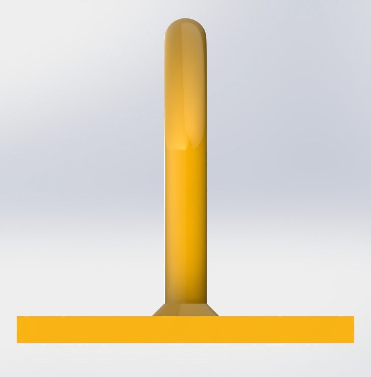
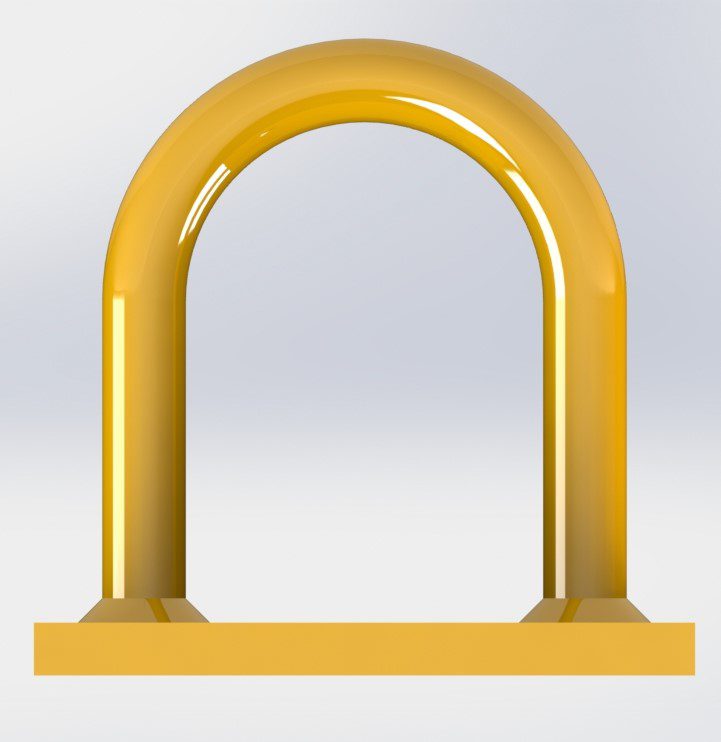
- A Solid Steel Support Beam from which 3 No. Tubular Anchor Points were suspended to secure the Sensory Swings from.
- Multiple Affixing Points allow the frame to be bolted into the existing Room Structure & Rubber Matting beneath the feet allow for a stable footprint.
- RAL-1007 Yellow Painted finish.
Display Stand
Requirements
The following requirements were noted prior to the design of the Display Stand
A lifting capacity of 100kg was required for the maximum lift.
- The Display Stand was required to achieve a height of lift of 3.0m.
- It was also required to be capable of disassembled and stored in a 1.0m x 1.0m crate.
- It was also required to be capable of being assembled by 2 people.
Solution
The solution provided was a Bespoke Display Stand complete with:
- A SWL of 100kg
- A SHS design capable of being broken down and packed into a 1.0m x 1.0m crate.
- A lightweight design which could be assembled using two staff members and a fork truck.
- RAL-1007 Yellow Painted finish.
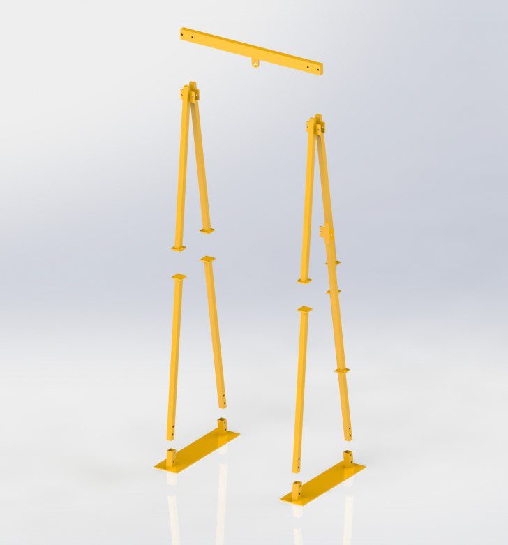
Exploded View Iso (001)
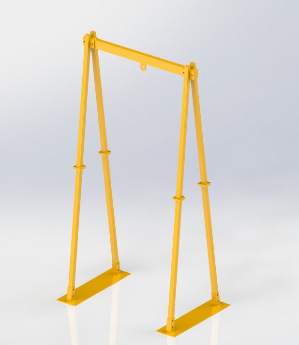
Iso View (002)
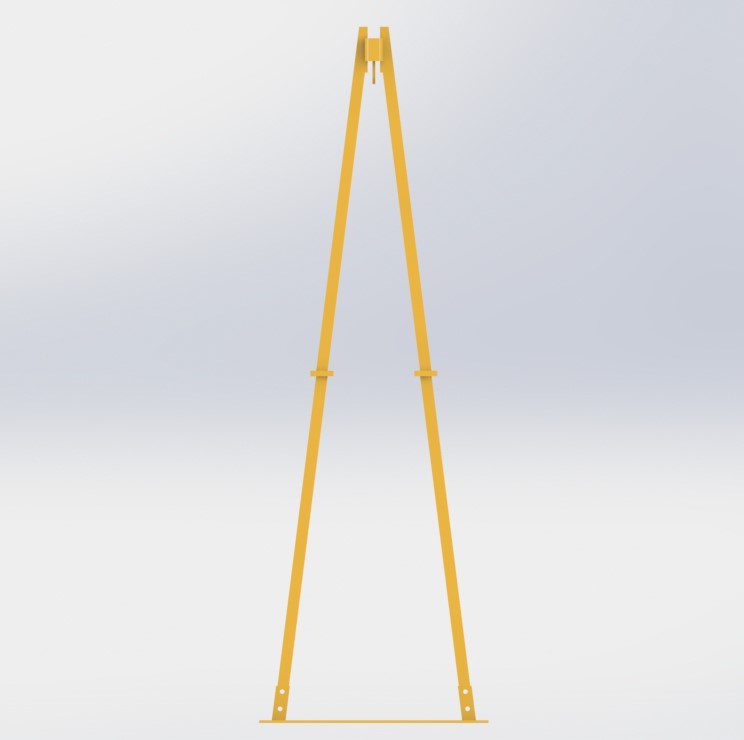
Side View (002)
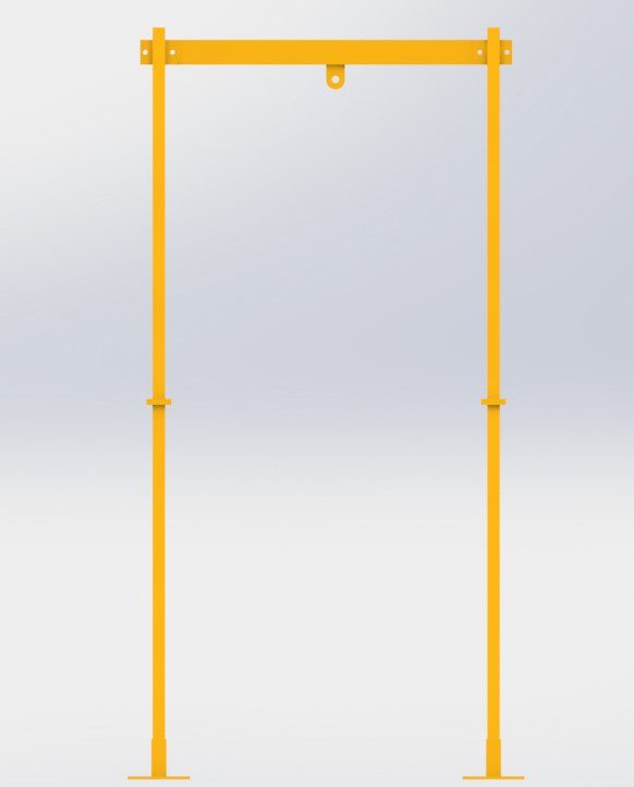
Elevation View (002)
Iso View
Top View
Side View
Elevation View
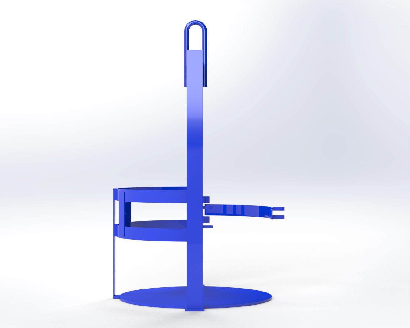
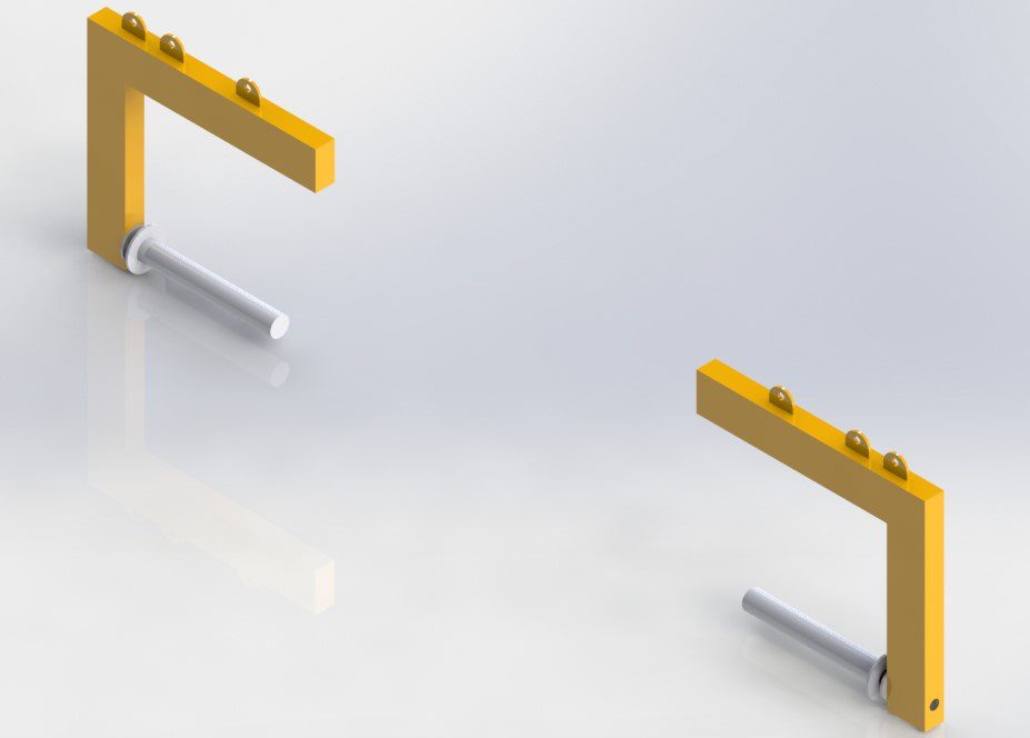
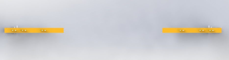
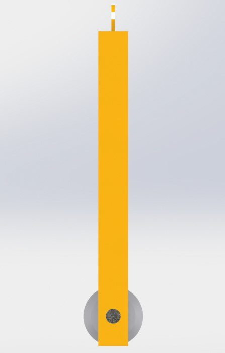
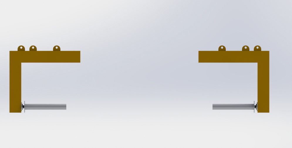
DLPE Roll Lifter
Requirements
The following requirements were noted prior to the design of the LDPE Roll Lifters
A lifting capacity of 2,000kg was required for the maximum lift.
- The Roll Lifters were required to be used in tandem to hold an LDPE roll of various overall lengths to support them on both ends.
- It was also required to be capable of allowing the LDPE Roll to be unravelled while on the lifters.
- It was also required to be capable of being used with either a spreader beam above or separate fork trucks.
Solution
The solution provided was a Bespoke LDPE Roll Lifters complete with…
- A SWL of 2,000kg
- A Solid Steel EN24T bar to support the rolls encased in a tubular steel shroud complete with internal bearings and support collar to allow the rolls to be unravelled while still secure.
- Multiple lifting points on each lifter to allow the roll to be balanced regardless of position.
- RAL-1007 Yellow Painted finish.
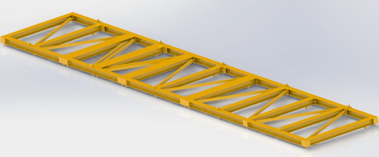
18T Modular Frame – Iso View
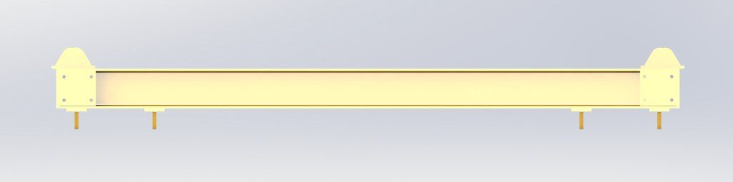
18T Modular Frame – End View
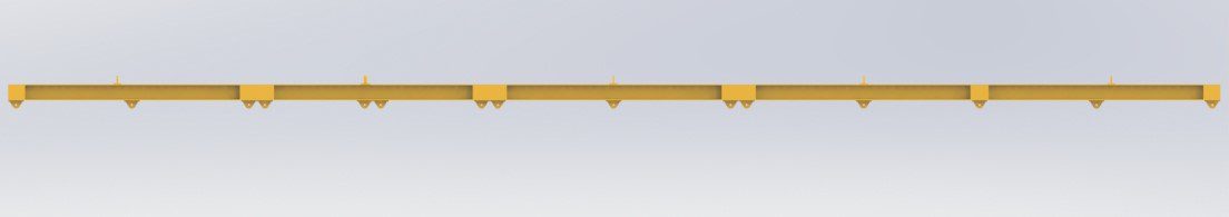
18T Modular Frame – Plan
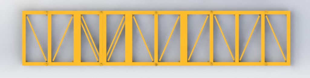
18T Modular Frame – Elevation
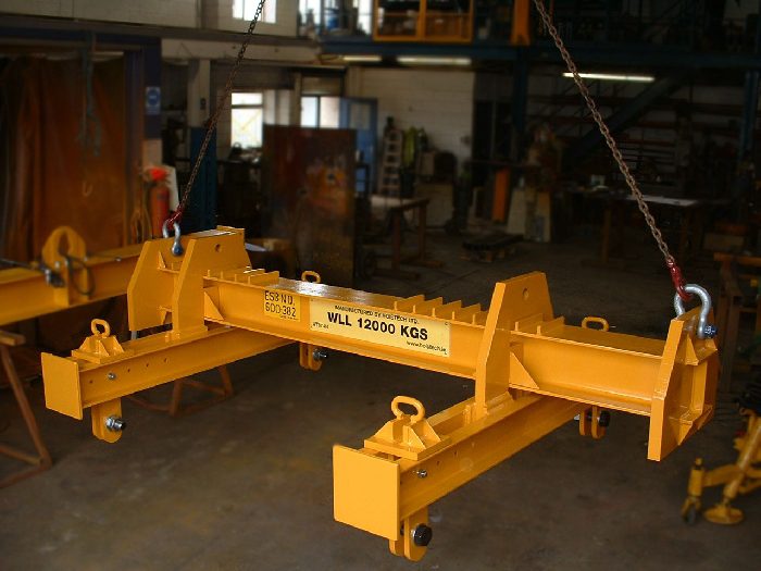
18T Modular Lifting Frame
Requirements
- A lifting capacity of 18,000kg was required for the maximum lift.
- The Lifting Frame had to be comprised of multiple modular pieces to allow it to be used with a number of different component sizes and weights.
- The Lifting Eyes had to be capable of being connected to an overhead Crane Hook at a number of different points to facilitate the modular design.
Solution
- A SWL of 18,000kg
- A 3 piece modular design which comprise of 3 No. 4m long sections each capable of lifting 6,000kg individually.
- 3 No. 4 Leg Sling Attachment points to allow the modular pieces to be used together or in whatever format was required.
- RAL-1007 Painted finish.
Adjustable A-Frame
Requirements
The following requirements were noted prior to the design of the Adjustable H-Frame
A lifting capacity of 1,000kg was required .
- The H-Frame was required to be adjustable along both axis to allow for use lifting pods of various dimensions.
- It was also required to have a single central lifting point to account for minimal headroom.
- Solution
The solution provided was a Bespoke Sensory Room Swing Frame complete with…
- A SWL of 1,000kg
- A modular design incorporating SHS frame members and an adjustable bolted connection to account for pods of differing dimensions.
- Multiple Drop Points to allow for a 4 No. Drop Lug Solution or a 8 No. Drop Lug Solution
- RAL-1007 Yellow Painted finish.
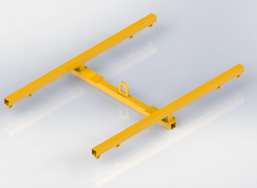
Vision Built Adjustable H-Frame – Iso View
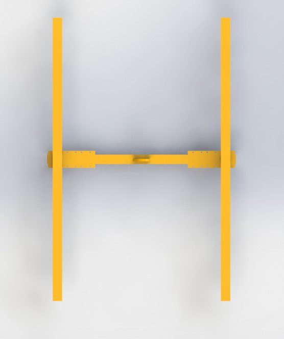
Vision Built Adjustable H-Frame – Plan View
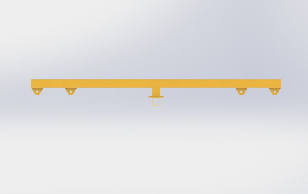
Vision Built Adjustable H-Frame – Side View
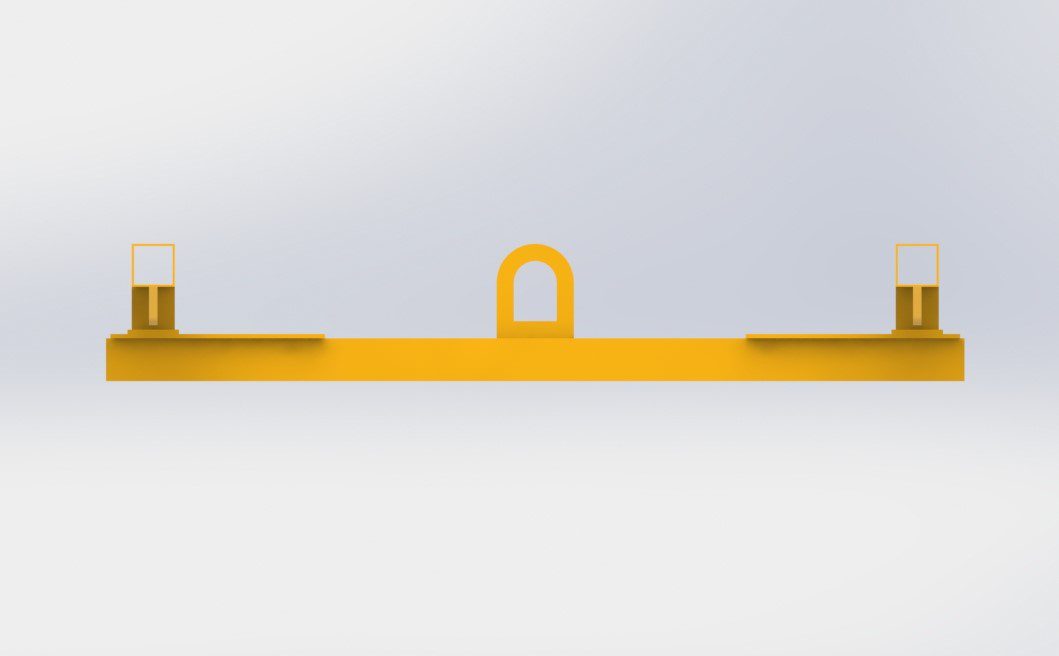
Vision Built Adjustable H-Frame – Elevation
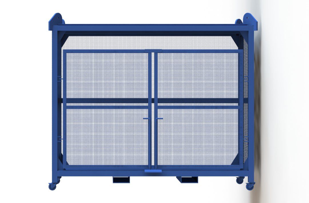
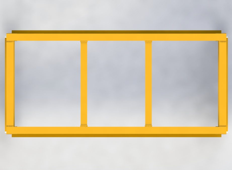
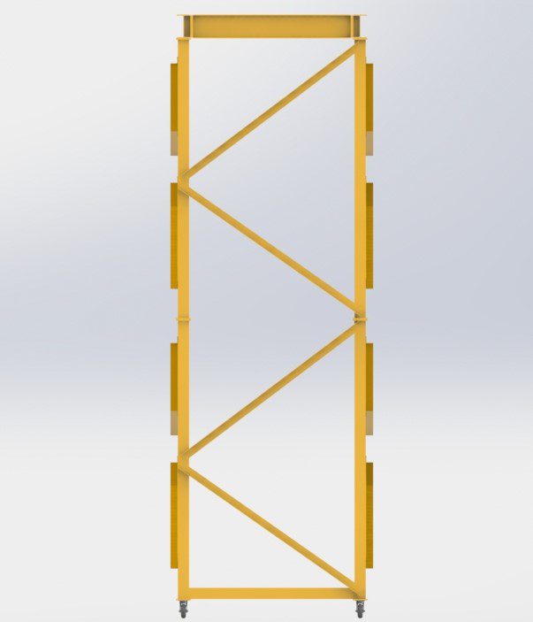
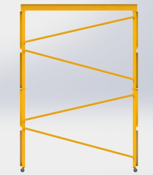
Pallet Gates
Requirements
The following requirements were noted prior to the design of the Pallet Gate.
- The pallet gate required mounting points to an existing plywood floor sitting on top of structural steel flooring supports.
- The pallet gate required weld mesh along the walls and revolving gate to prevent loose items falling off of the pallet onto staff working on the floor below.
- The revolving section was required to be light weight so as to be capable of being moved from an open to closed position by a single operator.
Solution
The solution provided was a secure pallet gate complete with…
- Easy revolving gate section pivoting around two pin joints.
- Light weight Box Section Frame & Weld Mesh wall protection.
- Independent wall sections to be bolted through wooden flooring into structural steel supports.
- RAL-1007 Yellow Painted finish.
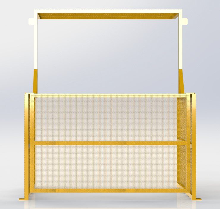
Pallet Gate – Front View
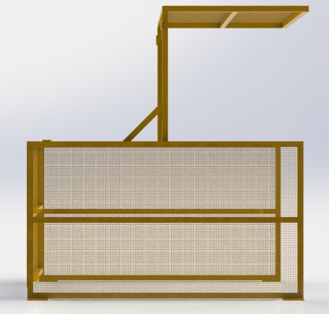
Pallet Gate – Side View
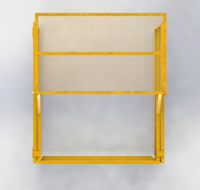
Pallet Gate – Top View
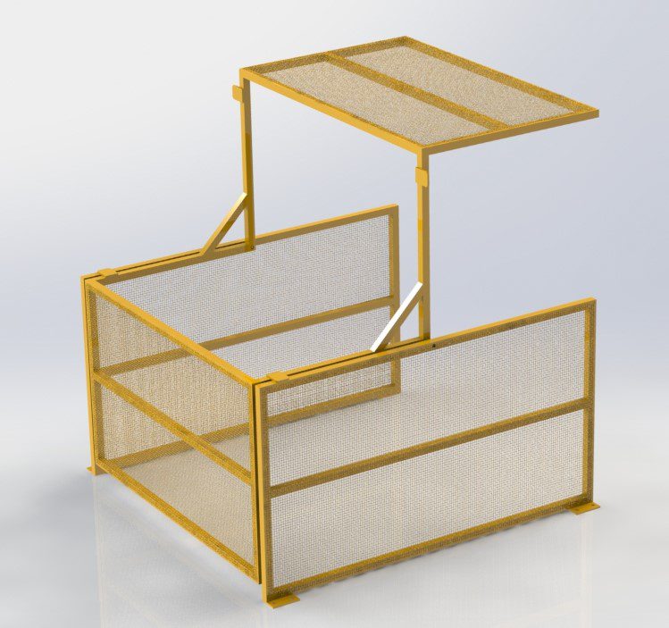
Pallet Gate – Iso View
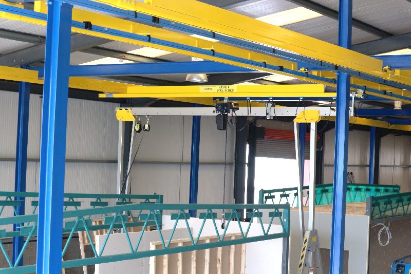
Gallows Monorail System
Requirements
The following requirements were noted prior to the design of the Monorail System.
A lifting capacity of 250kg was required for the maximum lift.
- The Monorail System was required to run along the length of a row of chemical dip tanks of 27.0m
- 2 No. electric chain hoists were required to run independently along the monorail to allow multiple samples to be dipped simultaneously.
- Solution
The solution provided was a Gallows System Monorail complete with…
- A SWL of 250kg
- 10 No. Gallows posts spaced 3.0m apart to complete a 27.0m long system.
- 2 No. electric chain hoists with pendant control.
- RAL-9010 White Painted finish.
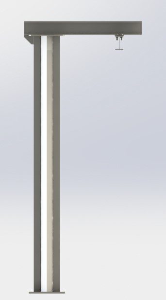
Individual Gallow..
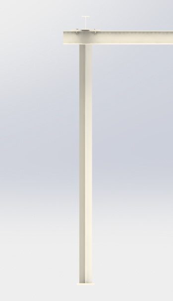
Individual Gallow…
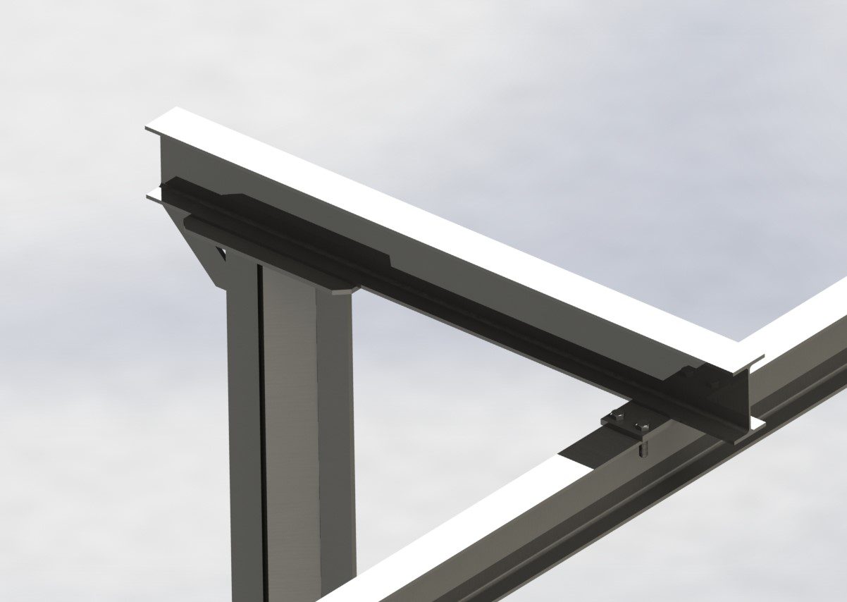
Gallows
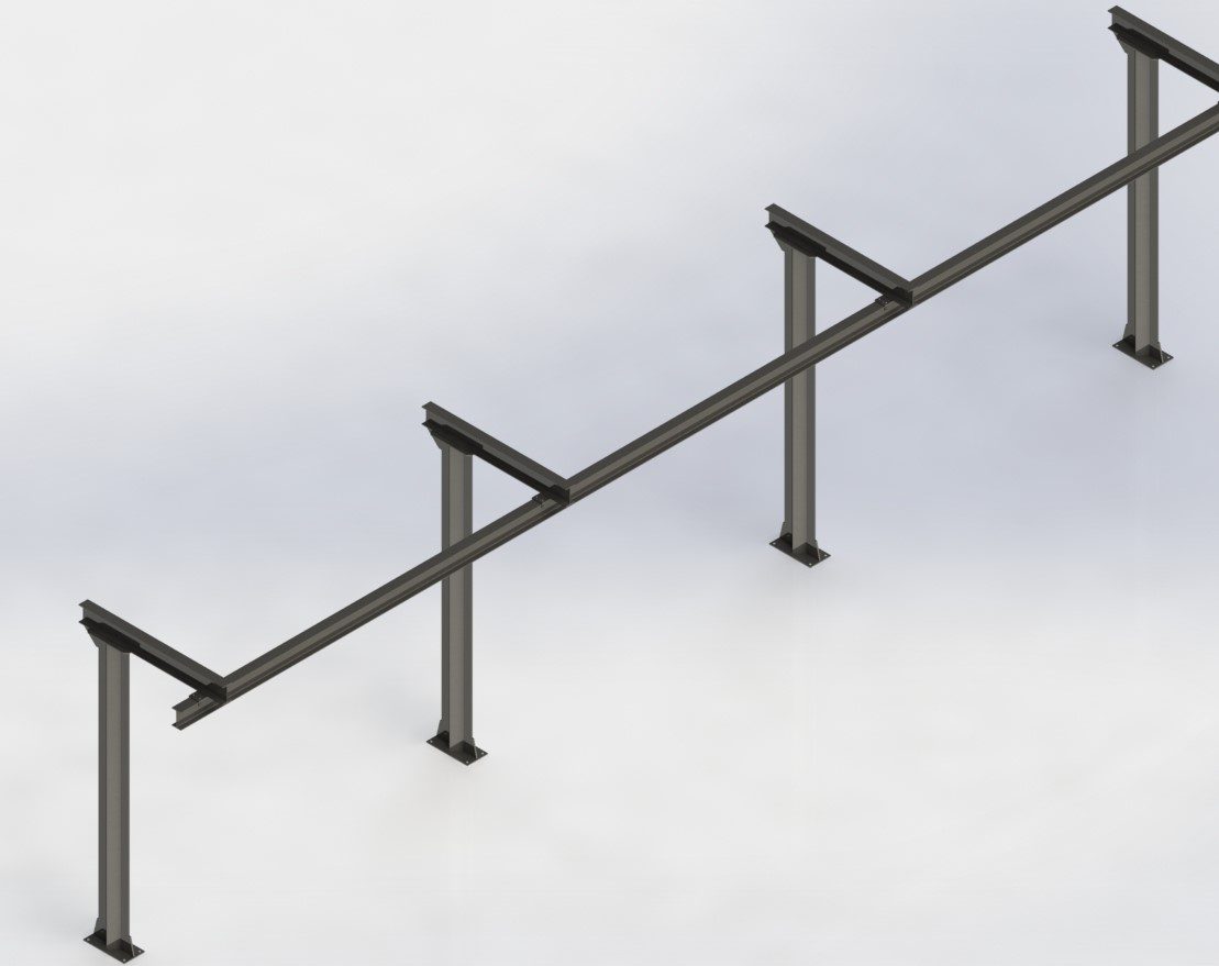
Rail System
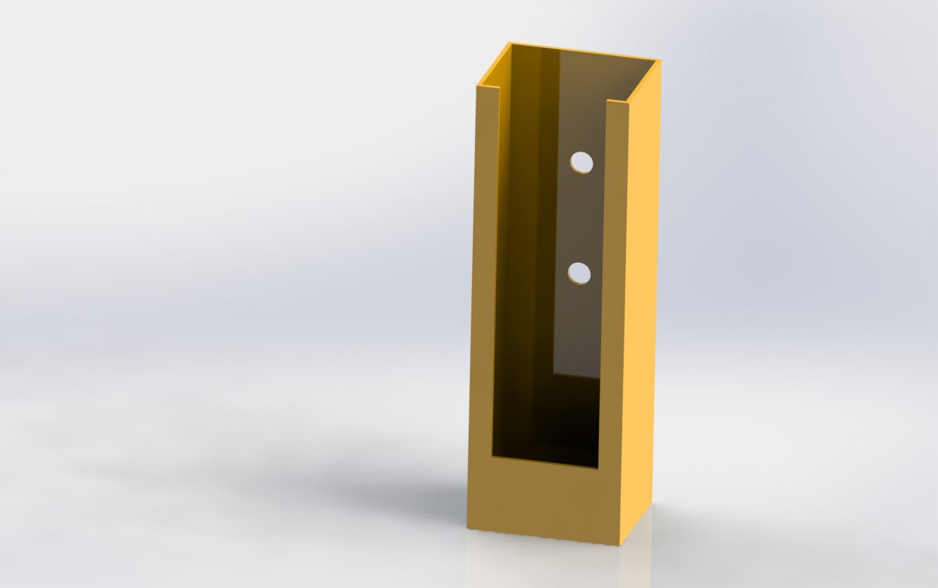
Hoist Pendant Holsters
Scope
The client had existing pendant controls for Monorail Systems with electrically powered hoists & trolleys. They required permanently mounted holsters for the pendants to prevent entanglement with staff.
Requirements
The following requirements were noted prior to the design of the Pendant Holsters.
- The pendant holsters required mounting points to a variety of existing structures including concrete walls, steel stanchions & existing machine bodies.
- There were two different sized pendants which required 2 different sized holsters to appropriately house the pendants.
- The were required to be easily visible by staff when out on the floor.
Solution
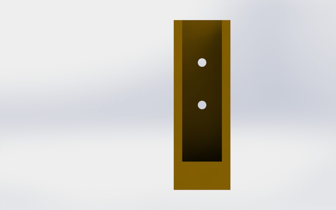
The solution provided were 2 No. Pendant Holster designs complete with…
- 2 No. Mounting holes on the back of the Holster to allow for simple mounting to the various structures required.
- Light weight sheet metal construction with easy access to buttons when stored in the holster.
- RAL 1007 Yellow paint finish to ensure easy visibility.

Holster 1 – Elevation View
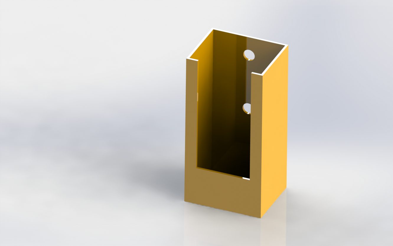
Holster 1 – ISO View
Holster 2 – Elevation View